Type: Search/Combat Robot
Weight: 100 lbs
Body: Aluminum Frame
Power: 100 in-lbs of torque
Control: 900 MHz RC
Speed: 6-10 mph
Weapons: Battle Axe, Saw Blades
Other:Robot Arm
Competition:UIUC Engineering Open House
Year: 2000
Results: Winner of Most Impressive Arsenal
|
|
Participants and History
 The 00-Astro team is comprised of Aaron Trask and
Mariusz Zaczek. The name
of the vehicle is Live and Let Die which is the name of a James
Bond (007) movie. Since our team name is a sort of take on the 007 theme,
we decided to name our car after a cool Bond movie title.
The 00-Astro team is comprised of Aaron Trask and
Mariusz Zaczek. The name
of the vehicle is Live and Let Die which is the name of a James
Bond (007) movie. Since our team name is a sort of take on the 007 theme,
we decided to name our car after a cool Bond movie title.
Competition Description
|
The actual competition took place on March 3th and 4th, 2000. This design competition
is open to many schools from around the midwest area and typically involves over 30
different teams. While many teams simply use slightly modified RC cars, there are a
few completely designed and built vehicles. The design competition is sponsored by
Advanced Micro Devices (AMD) and typically draws the largest crowds during the Engineering
Open House.
|

|
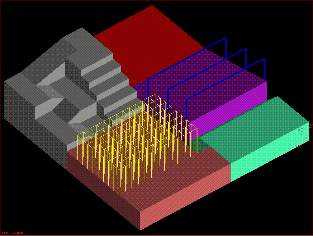
Course
|
For this year's competition the field was a race through an obstacle course.
The theme was "Mission: 2000 - Save the Engineers", where each robot was to
capture 3 small figures (engineers) along the route. The first stage of the
course was a field of mines followed by a slippery 15 degree incline upon
which three curtains of steady water came down...this required that the
vehicle be waterproof.
|
After the incline was a three foot drop off into a pit of foam blocks. Next came some
flat ground before the robot vehicle was to enter an area "corn stalks" ... represented
by overhaning wooden dowels. The final challange was to reach the peak of a mountain.
This could be done in one of two ways: either climbin five 1 foot steps or simply drive
up a series of small inclines.
Unfortunately, the layout of this course was too much in favor of small RC cars rather
than self-built robot vehicles.
|
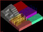
3D Course Drawing
|
Vehicle Description
This vehicle is composed of a machined aluminum body. The wheels are 20 inches in
diameter and are fixed - tank steering is the control method. With all equipment
attached the vehicle weighed in excess of 100 lbs and was able to move at a brisk
speed of 6 mph. Each wheel had it's own motor giving it over 100 in-lbs of torque.
In addition, this robot had interchangable parts that included a robotic arm and
offensive weapons.
A final touch included a color tv camera mounted on the vehicle which was connected
to an RF transmitter and sent to a remote television where the live feed was recorded.
|
Demolition Mode
|
Robotic Arm
|
During the regular round the vehicle had an attached 2 link robotic arm attached
to a rotating base. At the end of the second link was a home-made gripper. The arm
was able to swivel around at the base and raise/lower both links of the arm. The base
and links are actuated by 12 VCD Pittman motors while gripper was actuated by a high
torque server.
|
|
For the demolition rounds the arm was replaced with some offensive weapons. These
included a set of 3 vertically placed rear saw blades, 1 front horizontal saw blade, and
a side mounted battle axe. The saw blades were all actuated by 9.7 VDC portable drills
which were modified with gears and chains to rotate the blades. The blades were turned on
only when the joystick button was depressed otherwise they were off. The battle axe was
fixed but the ability of the vehicle to rotate in place allowed for this battle axe to be
used like a swinging bat ... i.e. to slap other cars around.
|
Battle Axe
|
Control System

M68332 BCC
|
The control system for this vehicle was designed and built from scratch. The main
components were two Motorola 68332 microcontrollers, graciously donated by the
Motorola Corporation. One controller was placed on the robot and the other was
connected to the main Saitek's Cyborg 2000 joystick. The communication was done through RF using
Linx Technologies HP-II series RF modules with a frequency of ~900MHz.
|
|
The two microcontroller were programmed in assembly language and circuits were built to
interface the controllers with the joystick and motors. The assembly language programs
required the use of the Serial Communications Interface (SCI) and Timer Processing Unit (TPU)
modules. The SCI was used to generate a serial stream of data that was sent through the
RF chips to the receiver SCI. The vehicle code used the TPU to generate the necessary Pulse
Width Modulated (PWM) waveforms for controlling the Pittmans and servos. In addition, a
24 VDC speed control circuit was designed with the aid of Prof. Uribe. (Code available below)
|
Speed Control Circuit
|
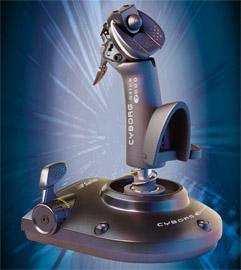
Saitek Cyborg 2000
|
The Cyborg 2000 joystick was connected to the Motorola 68332 microcontroller by
using the ADC0808 Analog-to-Digital converter. This converted the potentiometers
inside the joystick into digital values from 0V to 5V DC. There were a total of three
potentiometers: two on the joystick for the forward/reverse and left/right motion
and a third on the front of the joystick used to adjust the gripper.
|
|
The hat button
on top of the joystick controlled the base of the robot arm - rotating the base and
raising/lowering the first link. Two of the big buttons were for moving the 2nd link
while the third button was not active for the robotic arm. The trigger was to be used
for opening/closing a container device which was never finished.
|
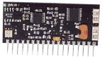
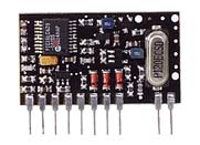
Linx Technologies - HP-II RF
|
Competition Results
The competition went pretty well for us in the beginning. We were one
of only a few vehicles that could make it up the wet incline and reach as
far as the mountain - during the regular rounds. Unfortunately, our
design was too big for the course, which most suited small RC cars.
In fact, we had so much power that one time we actually flew over the back
barrier (and partially into a small crowd) after taking off from the
slippery ramp. No one was injured but our color camera was able to capture
the entire flight. The stairs posed a big challenge for our vehicle. Because
of our extreme weight we could only make it up the first step. During some
minor pre-competition tests we noticed that we could make it up only a first step
but we thought our batteries were limiting us. We had so much torque that we
litterally flipped ourselves over when we ran into a wall - the vehicle gripped the wall
and climbed it until it flipped over. Unfortunately, our design flaw was
discovered much too late.
We expected the demolition rounds to bring us much better success. Based on
the strength of our recent "Most Impressive Arsenal" award, we felt that the
demolition rounds were ours. Unfortunately, one major problem occurred at the
start of a demolition round that resulted in our vehicle breaking all of it's
weaponry and causing interal circuit damage. A RF video camera of the
Competition Committe caused severe interference with our control system...litteraly
taking over our car and smashing it into a wall. This was not discovered in time
even though a RF spectrum analyzer was present for the competition to monitor
interference. We were still able to compete but we were "weaponless". It was truly
a dissappointment to work so hard on this project and then be destroyed by outside
interference rather than during an actual competition.
Credits/Thanks
This robotic vehicle was completely designed and built by Aaron Trask and
Mariusz Zaczek.
Aaron was in charge of the mechanical systems which included the design and
construction of the vehicle body, mounting the motors, building the arm and
gripper, mounting the weaponry. He also made suggestions for the control
system and helped with making several circuits.
The control system was the designed, built and programmed by Mariusz Zaczek.
Mario made the various circuits for the motors, servos, joystick, RF modules.
He also wrote the receiver and transmitter codes from scratch. The codes are
available below. In addition, he helped assemble parts of the vehicle and made
some design suggestions.
The design of this vehicle started in September of 1999. In late December 1999 and
early January 2000 the car was beginning to take form and the control system code
was being written. The base of the car was completed in early February while
the weapons and robotic arm was finished by late March. The circuits were finished
by early February but the control code was fully completed by late February.
We'd like to express our deepest thanks to the following people and organizations
- Motorola Corporation - for graciously donating their M68332 microcontrollers which
were the most vital part of this robot.
- ADSL - Prof. Uribe - for allowing us the use of the Advanced Digital Systems Lab
and for his help in the design of the speed control system. Prof. Uribe has been
a great help and a great teacher.
- UofI Everitt Machine Shop - for mounting gears on our wheels and for allowing us the
use of the student machine shop
- Charles Melear - For graciously answering many of our questions regarding the M68332
- Jake Janovetz - For allowing us to use his old robot buggy code as an example and
for helping us figure out some circuits and problems.
- Casey Smith - For answering many of my M68332 questions and electrical engineering questions
- Mr. Wiatr - For donating his equipment to help us build the vehicle.
|