3-D Profile Scanner
Aaron Trask
Mariusz Zaczek
ADSL
Spring 1999
1.0 Introduction
Recreating physical objects into three dimensional computer graphics can be an expensive and time-consuming task. Today, many methods for scanning physical objects and recording dimensional information exist. One type is to probe the surface of an object and record the probe position. This method is usually done with expensive and bulky machines, but the 3-D Profile Scanner (3DPS) presented here is a cost effective alternative to the hobbyist. The 3DPS has a 2mm probe giving a resolution of 2mm. It can scan a 150mm cube and record the profile as a set of points, which can be meshed to display the surface of the scanned object.
2.0 Mechanics
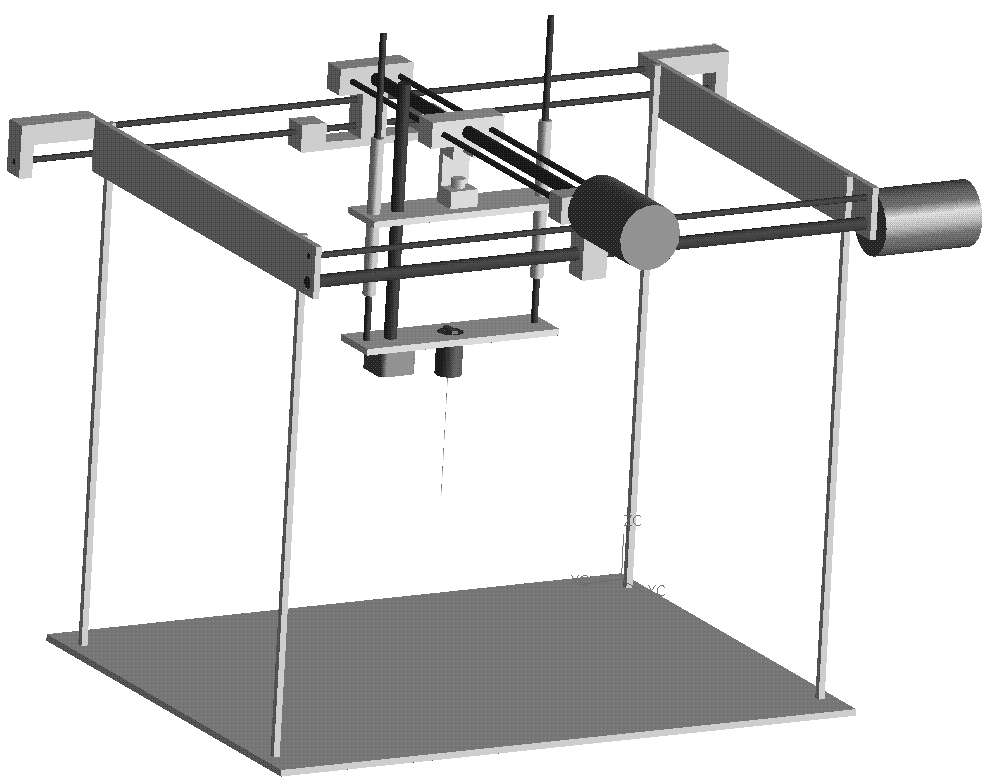
The 3-D Profile Scanner (3DPS) uses a basic 3-axis table [Fig. 2.1]. All three axes slide on rails with linear bearings and are pushed by lead screws. DC stepper motors, giving a resolution of 1/12mm per step in the x-axis and y-axis and a 1/77mm per step resolution in the z-axis, power the lead screws.
Figure 2.1: 3-Axis Table
The probe consists of a limit switch with a return spring to push the probe to rest [Fig 2.2]. As the probe is lowered and comes into contact with the object being scanned, the limit switch is pressed. This sends an interrupt to the program and the positions of the three stepper motors are recorded.
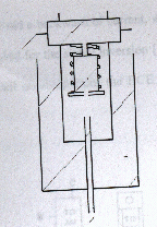
Figure 2.2: Probe Design
3.0 Electronics
3.1 X and Y direction motors
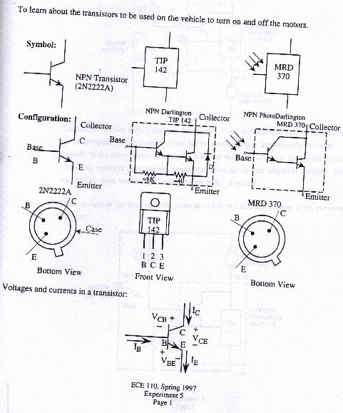
The motors used for the x and y positioning of the probe are 24 VDC, 1.26 A Werner Electric stepper motors. Each motor has four color wires (black, red, yellow, brown) that are used to initiate the stepping action. For each step pulse the motor is able to turn 15 degrees. This motor is an a 3-phase motor that uses the common wire (black) as the LO (ground) or HI (24 VDC) wire while the HI or a LO signal is rotated through the other three wires in a red-yellow-brown sequence (the order is reversed to generate opposite rotation). For this 3D scanner, the black wire was connected to HI using a 12 VDC source rather than the rated 24 VDC which was not necessary [Fig. 3.2]. The other three wires were connected to the signal obtained from the computer. A TIP142 NPN Darlington transistor. assigned to each of the three signal wires, was used to rotate a HI signal to control the action of the stepper motor [Fig. 3.1 and Appendix]. The original signal, that is obtained from code via the parallel port, is first inverted prior to reaching the TIP142 transistor primarily to avoid a back wash of current which may hurt the parallel port. A SN54/74LS04 Hex Inverter (see appendix for data sheets) is used for the signal inversion. The circuit design was taken from motor control circuit obtained from the ECE 110 Laboratory Manual by Prof. Ricardo B. Uribe (p 43).
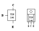
Figure 3.1: TIP 142 Darlington Transistor (Uribe, 1997)
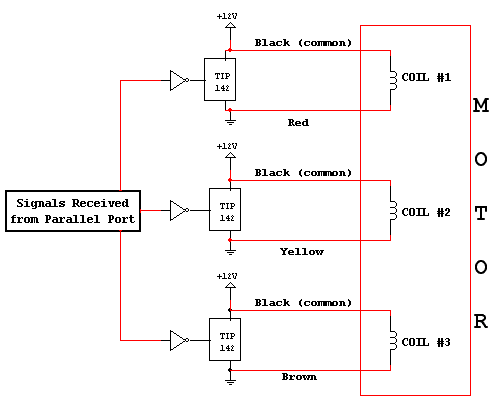
Figure 3.2: X & Y Stepper Motor Circuit
3.2 Z Direction Motors
The z-direction motor (Astrosyn Size 17) uses the typical application circuit found in the data sheet for the LMD18245 [Fig. 3.3 and Appendix]. M1 through M4 pins are set to the 5V supply, the Direction pins are the signals from the parallel port, and the Brake pins are set to ground.
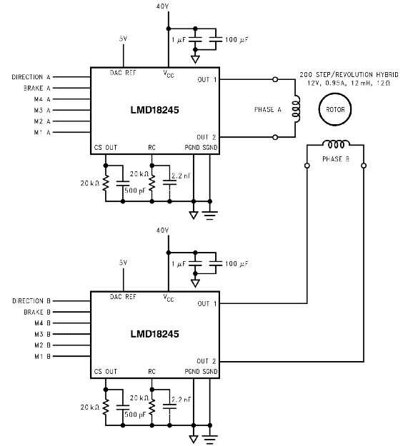
Figure 3.3: Z Stepper Motor Circuit (National Semiconductor, 1998)
3.3 Computer Interface
The parallel port of a PC is used to control the entire scanner assembly which includes all motors and interrupt switches. A guide on the use of the printer port for control and data acquisition is attached in the appendix. Pins 2 through 7 (DATA) generate control signals for the three motors which correspond to an eight bit word where bits 0, 1, 2 control the y-direction motor, bits 3, 4, 5 control the x-direction motor and bits 6 & 7 control the z-diection motor - the most significant bit (MSB) being 7. Figure 3.4 below shows the pin assignments for a parallel port of a PC.
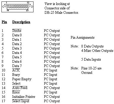
Figure 3.4: Parallel Port Pin Assignments
As mentioned before, the signal received from the parallel port is inverted prior to reaching the motors. As a result, while a logic 1 (HI) is shifted through the wires of the motors, to control the stepping, and logic 0 (LO) must be generated by the code and sent through the parallel port. A typical code output for the DATA word would look as follows: (bit 7) 11 110 110 (bit 0). The zero value in bits 0,1,2 and 3,4,5 is shifted rotated through to generate a step. Bits 6,7 use a sequence specified by the LMD18245 chip to control the z-direction stepper motor [Appendix].
In order to output data via the parallel port pins, the address of the parallel port must first be determined for the particular PC being used. This can be done by using the DOS debug program to display the memory locations 0040:0008 by typing at a DOS prompt (Anderson):
DOS PROMPT> debug
debug mode: -d 0040:0008 L8
example result: 0040:0008 78 03 78 02 00 00 00 00
For the above example result, the LPT1 (1st parallel port) address is 0x0378 (hexidecimal) while LPT2 is 0x0278 and LPT3 and LPT4 are not assigned. For the computer used by this project the DATA word was assigned to the 0x0378 address while the corresponding STATUS and CONTROL words were assigned to 0x0379 (DATA+1) and 0x037a (DATA+2), respectively. The STATUS word is used by the mechanical interrupt which is generated by the limit switch when the probe makes contact with the part surface. The schematic of the connection necessary for the interrupt are shown in the figure below. Pin 11 is an input pin of the parallel port that is scanned continously during the vertical (z-direction) movement of the probe. When the limit switch (or push button) is engaged the input of pin 11 is connected to ground (pin 18) which alerts the code to stop the probe movement and record the current position.
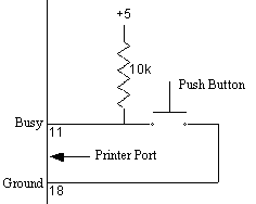
Figure 3.5: Schematic of Mechanical Interrupt Circuit (Anderson)
4.0 Code Description
The control code used to automate the action of all motors on the 3D scanner is written in the C programming language - C++ can be used with slight modifications. A copy of this code - scanner.c - is attached in appendix A of this report. This code was compiled using a Borland C compiler for DOS and Windows – the run file generated is called scanner.exe. Output of each scan is sent to a file called scan_out.txt for later retrieval
4.1 Program Walk-Through
In order to run the scanner program with minimal problems it is advised that the computer be restarted in DOS mode. To run the program, enter the directory containing the executable file as well as a file called: EGAVGA.BGI which is the video driver required to display graphics in DOS.
Upon exectution of the program the first prompt instructs the user to initialize the position of the probe by moving the tip to the lowest plane possible – this will set the zero (0) position of the z axis. An "Interrupt" message will be generated on the screen to instruct the user to position the probe at the starting scan location for the part on hand. This starting location corresponds to the upper most (z-axis) position of the probe in the lower left portion of the scan area [Fig. 4.1].
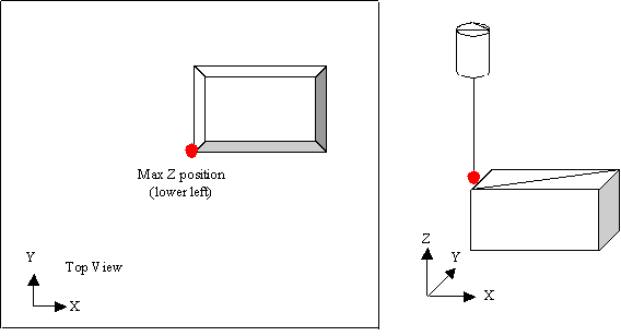
Figure 4.1: Starting Probe Position
Once the upper most position is locked in place by hitting ENTER, the program will prompt the user to input the maximum x and y dimensions of the part in milimeters. This is followed by a request for the maximum x and y step distances in milimeters – i.e. how far should the probe head move in the x and y direction during the scan. Upon completion of this initialization the screen will clear and a main opening screen will appear displayin the text: "3D Scanner ... Zaczek, Mariusz & Trask, Aaron". Scanning will start when the user hits the ENTER key.
The scanning of the part is a raster type scan shown in the figure below. The probe starts at the maximum height in the lower left portion of the part [Fig. 4.2]. It descends the probe until contact is made and then returns. Next the probe proceeds along the +y axis stopping after one after the specified distance entered during the initialization process. Once again, the probe lowers until contact is made and finally retracts. This process repeats until the maximum y position is reached, during which time the probe will move over one specified step to the right and repeat the previous process but in the reverse direction.
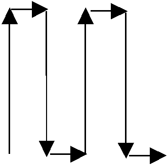
Figure 4.2: Scanning Motion of Probe (Top View)
During the scanning of the part, points are graphically displayed to the screen representing the probe contact locations. Upon completion of the scan the entire image on the screen will begin to rotate in 3D space and thus the contours of the part can be seen with more detail. Rotation and 3D perspective code examples are attached in the Appendix. This code was used to complete the scanner program.
(Note: Due to the limitations of the motors, scan times even for small parts can be long. For example a part of max height of 2cm having 200 points scanned can take approximately 1hr)
5.0 Conclusion
The 3-D Profile Scanner has been a successful project but there are still many possible additions and improvements that can be made to it. In its current state this scanner can only scan the contour of very simple shapes. Curved surfaces pose difficulty because the probe tip tends to slip off and follow the surface face. An improvement for this case may be to use a rubber tip on the probe as well as to stiffen the probe itself so that it does not bend and flex. In addition, the vertical screw used, used to move the probe up and down, has a bend in it and should be corrected to get more precise movement while avoiding the wobble induced due to this imperfection. The current 3-D display only joins each point scanned by a single line and a true wire-frame representation woud be the next step to improve this . A final improvement would be to use shading to display the part a a fully three dimensional image.
References
Anderson, Peter H., "Use of a PC Printer Port for Control and Data Acquisition",
http://et.nmsu.edu/~etti/fall96/computer/printer/printer.html, 1999
Bikker, Jacco, "Building a 3D portal Engine",
http://www.flipcode.com/portal/issue5.htm, 1999
Uribe, Ricardo B., "Introduction to Electrical and Computer Engineering - ECE 110
Laboratory Notes and Manual" , Spring 1997
The following images show the TIP 142 (Darlington Pair) circuits. The
TIP 142 was used for control of the of X & Y motors because of the need
for a 12 VDC supply (They were actually 24 VDC but 12 VDC was enough).