Sensor Glove and Robotic Hand
Advanced Digital Systems Lab
Spring 2000
Aaron Trask & Mariusz Zaczek
1.0 Introduction
The sensor glove allows an operator to move a computer-generated hand or a robotic hand like a puppeteer. Each joint of the human hand (only the fingers) is encoded and then converted to an angle command. The human hand has twenty degrees of freedom not including the wrist. Each degree of freedom is encoded with a potentiometer. The voltage across each potentiometer is converted to a binary number with an A/D converter. This number is then converted to the corresponding angle for each joint.
2.0 Mechanics
The human hand has twenty degrees of freedom (see Figure 2.1). Each finger has two degrees of freedom where they meet the palm and then one degree of freedom for each of the remaining two joint per finger. Figure 2.2 explains the terminology adopted for this project. The glove is constructed to encode each joint without restricting the operator’s movement.
Figure 2.1: Twenty Degrees of Freedom of the Human Hand
Figure 2.2: Adopted Terminology
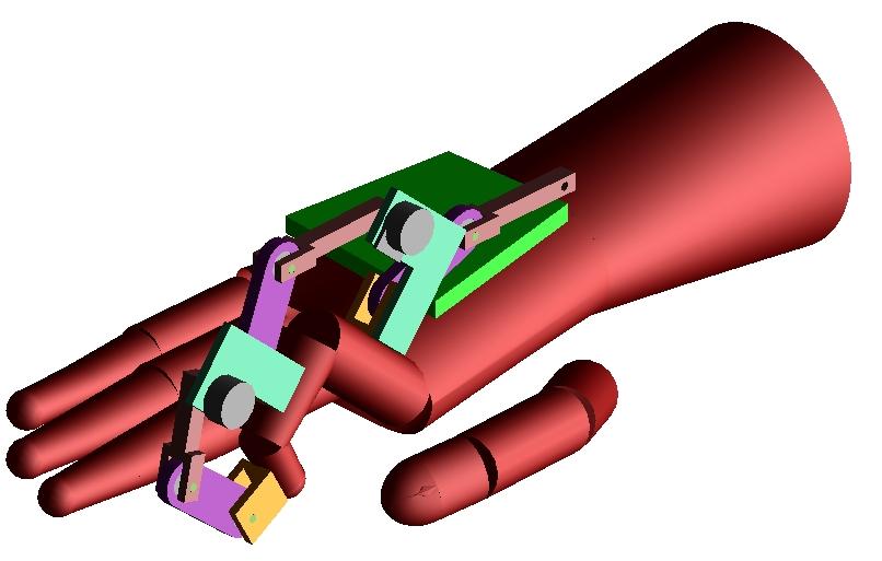
The first glove design consists of an exoskeleton surrounding a golf glove to protect the users skin. The exoskeleton is composed of aluminum plate and steel shafts, which allow free motion of the users hand (see Figure 2.3). A reference plate for all of the fingers is mounted on the back of the glove. On the reference plate, five joystick potentiometers are mounted for each compound knuckle joint (not shown in Figure 2.3). From these joystick potentiometers, a two-link joint is attached. The other end is then bracketed to the top section of the finger. Attached to the bracket is a potentiometer with a two-link joint. The other end of this two-link joint is bracketed to the middle section of the finger. This is repeated for the last remaining section. This design allows the mechanics to be mounted within the width of a finger so that there is no obstruction of movement. Each joint other than the compound knuckle must have a two-link joint in order to allow free movement since the axes of rotation are not coincident. The compound knuckle has the yaw axis coincident but the pitch axis requires a two-link joint since it is not coincident.
Figure 2.3: 3-D Modeling of the Sensor Glove Design
The current glove design consists of a spandex glove with a plastic exoskeleton. The plastic exoskeleton was made from thermoplastic, which can be easily formed when heated and hardens when cooled. The potentiometers are attached in a similar fashion as the old design.
3.0 Circuit
3.1 Original Circuit for use with Parallel Port
In order to control the 3D hand a connection to the sensor glove is required. This connection has been made via the standard parallel port of a PC. The potentiometers of the glove are analog devices but the computer is digital as a result a conversion of one is necessary. This can be done via an A/D (analog to digital) converter. The converter used to read the potentiometers of the index finger and thumb is the ADC0808 8-bit, 8-channel converter. Only eight channels are required since only 8 joints will be controlled. The A/D converter requires a clock with frequency between 640 & 1280 kHz to be able to perform all conversion. As we only had on hand a 2 MHz crystal oscillator (clock) a J-K flip-flop was used to halve this frequency and thus fit the required range. If a 1MHz clock is available then the flip-flop portion of the circuit can be avoided. The output of the 2MHz clock was tied to both the J and K inputs as well as the flip-flop's own clock input. The resulting output produced a 1 MHz signal.
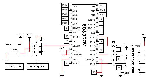
Figure 3.1: Control Circuit of Sensor Glove
Once the clock is connected to the A/D converter the potentiometers are connected to the IN# pins (where #=0,1..7). The A/D converter reads the voltage of a given potentiometer based on the values of the A, B, and C pins of the converter (the pins correspond to the 2, 3, and 4 pins of the parallel port). These pins represent the front connection of a multiplexer which takes this 3-bit signal to determine which of the eight potentiometers to read (2^3 = 8). The output of the A/D converter is through the eight pins labeled (MSB) 2^-1, 2^-2 etc. These outputs are then connected to the parallel port. Certain bit values are first inverted by using the hex inverter. This is required since certain pins inside the parallel port of the computer itself are hardware side inverted.
To successfully convert the potentiometer analog input to a digital output the A/D converter requires a sequence of initializations in order to read and convert each value. The timing diagram of the ADC0808 converter shows the required sequence quite clearly. For each potentiometer conversion the following must be done: First the START and ALE pins of the converter are set low to clear them. Next, the ALE pin is set high, shortly afterwards the START pin is also set high. Next the ALE pin is brought low and then the START pin is brought low. At this instant the conversion routine begins and after about 100 microseconds the conversion is complete. Finally, the output enable, OE, is set high and the A/D converter can read the data. Once done, the OE pin is again set low and the process can begin anew.
3.2 Motorola 68332 Circuit
In the current design two Motorola 68332 microcontrollers are being used to read the input from the sensor glove. The first microcontroller will read 12 inputs corresponding to 3 fingers while the second microcontroller will read the remaining 8 inputs, 2 fingers. The split was necessary because the robotic hand will require twenty servo controlled via pulse width modulated (PWM) signals and each microcontroller has only 16 channels on which to output PWM. The circuit for the first three fingers and the circuit for the next 2 fingers is nearly identical except that the second will read in fewer potentiometer inputs. The two circuits are the same as the circuit used in the previous semesters control system and thus will not be repeated. One major change is that the A/D converter used by the "3-finger" circuit will be replaced by the ADC0816. This new A/D converter has sixteen analog inputs. The final major change is that the parallel port is no longer used to read the A/D converter and no output to the screen is produced. Instead the
MC68332 takes the input and outputs the PWM signals to the corresponding servos, which will control the robotic fingers. Attached in Appendix B is the new code used on the MC68332 microcontroller.
4.0 Code Basics
The code attached in appendix B is downloaded to the MC68332 microcontroller via an attached serial port of the board. The AS32.exe program is first used to compile the program and the TELIX terminal program is used to connect to the MC68332.
Once activated, the code interfaces with the A/D converter and selects the analog inputs that are converted to an 8-bit digital signal, which is read by the MC68332. The code then computes the current position of the potentiometer and determines the PWM signal in order to set the corresponding servo to its correct position. The next potentiometer is then read and the process is done for every potentiometer attached and then repeated.
5.0 Conclusion and Future Work
The new sensor glove is not completed and the robotic hand is still under construction. Both are far along in the process of a prototype. The code and equations will be modified to allow a more precise control and corresponding simulated movement.
APPENDIX B: MC68332 Code
***********************************************
* *
* finger_3.s *
* *
* -Author : Mariusz Zaczek (zaczek@uiuc.edu) *
* -Date : 04/24/2000 *
* *
***********************************************
opt nolist
***********************************************
* *
* *
***********************************************
*
* EQUATES
*
FUNCNUM_3 equ $9999 * 12) PWM, 11) PWM, 10) PWM, 9) PWM
FUNCNUM_2 equ $9999 * 7) PWM, 6) PWM, 5) PWM, 4) PWM
FUNCNUM_1 equ $9999 * 3) PWM, 2) PWM, 1) PWM, 0) PWM
max_X equ $e8 * 222/256 +5 VDC
min_X equ $24 * 46 " "
max_Y equ $e1 * 215 " "
min_Y equ $1d * 39 " "
Servo_Period equ $28f6 * 20 ms
Servo_Max equ $037b * 1.7 ms
Servo_Min equ $016f * 0.7 ms
Servo_Mid equ $029d * Mid value ... 1.2 ms
Servo_Diff equ $020c * Diff between max & min = 1.0ms
* Finger #1 - Joint 0a
CHANNEL_0 equ $FFFF00 * CH 0 - PWM (control reg)
HIGH_TIME_0 equ $FFFF04 * ( high time )
PERIOD_0 equ $FFFF06 * ( period )
* Finger #1 - Joint 0b
CHANNEL_1 equ $FFFF10 * CH 1 - PWM (control reg)
HIGH_TIME_1 equ $FFFF14 * ( high time )
PERIOD_1 equ $FFFF16 * ( period )
* Finger #1 - Joint 1
CHANNEL_2 equ $FFFF20 * CH 2 - PWM (control reg)
HIGH_TIME_2 equ $FFFF24 * ( high time )
PERIOD_2 equ $FFFF26 * ( period )
* Finger #1 - Joint 2
CHANNEL_3 equ $FFFF30 * CH 3 - PWM (control reg)
HIGH_TIME_3 equ $FFFF34 * ( high time )
PERIOD_3 equ $FFFF36 * ( period )
* Finger #2 - Joint 0a
CHANNEL_4 equ $FFFF40 * CH 4 - PWM (control reg)
HIGH_TIME_4 equ $FFFF44 * ( high time )
PERIOD_4 equ $FFFF46 * ( period )
* Finger #2 - Joint 0b
CHANNEL_5 equ $FFFF50 * CH 5 - PWM (control reg)
HIGH_TIME_5 equ $FFFF54 * ( high time )
PERIOD_5 equ $FFFF56 * ( period )
* Finger #2 - Joint 1
CHANNEL_6 equ $FFFF60 * CH 6 - PWM (control reg)
HIGH_TIME_6 equ $FFFF64 * ( high time )
PERIOD_6 equ $FFFF66 * ( period )
* Finger #2 - Joint 2
CHANNEL_7 equ $FFFF70 * CH 7 - PWM (control reg)
HIGH_TIME_7 equ $FFFF74 * ( high time )
PERIOD_7 equ $FFFF76 * ( period )
* Finger #3 - Joint 0a
CHANNEL_8 equ $FFFF80 * CH 8 - PWM (control reg)
HIGH_TIME_8 equ $FFFF84 * ( high time )
PERIOD_8 equ $FFFF86 * ( period )
* Finger #3 - Joint 0b
CHANNEL_9 equ $FFFF90 * CH 9 - PWM (control reg)
HIGH_TIME_9 equ $FFFF94 * ( high time )
PERIOD_9 equ $FFFF96 * ( period )
* Finger #3 - Joint 1
CHANNEL_10 equ $FFFFA0 * CH 10 - PWM (control reg)
HIGH_TIME_10 equ $FFFFA4 * ( high time )
PERIOD_10 equ $FFFFA6 * ( period )
* Finger #3 - Joint 2
CHANNEL_11 equ $FFFFB0 * CH 11 - PWM (control reg)
HIGH_TIME_11 equ $FFFFB4 * ( high time )
PERIOD_11 equ $FFFFB6 * ( period )
include equ332.asm
org $9000
* org $e0000
* only when using own EEPROM chips
* dc.l $2ffc ; Power on/Reset stack pointer
* dc.l Start ; Power on/Reset program counter
*
* Start
*
* - This is where it all begins ...
*
Start
move.w #$2700,SR
clr.b SYPCR
* only when using own EEPROM chips
* bra.l csInit * Initialize chip selects
csInitReturn
move.b #$7F,SYNCR
* only when using own EEPROM chips
* lea bos,sp * Point the stack pointer to bottom
jsr TPUInit * Initialize TPU
jsr PortEInit * Initialize Port E (Input)
jsr PortFInit * Initialize Port F (Input)
jsr PortQSInit * Initialize Port QS (Output) 7pins
clr.w D1 * Start Pot counter at 0
*
* Main_Loop
*
* - Main program body.
*
Main_Loop
jsr CaptureData * Get data from pots and i/o
jsr CalculateData * Calc Data and update servo
bra Main_Loop * Loop back ...
*
* CaptureData
*
* - Reads Port E for potentiometer input and updates PWM signals
*
CaptureData
* Start sequence for reading potentiometers
* bits 3,2,1,0 will be for pot select (0000, 0001, 0010, etc.)
* bit 4 will be for ALE
* bit 5 will be for START
* bit 6 will be for Output Enable
jsr Delay1u
jsr Delay1u
jsr Delay1u
jsr Delay1u
*
* Read next potentiometer ...
*
* Increase pot counter by 1
Counter
cmp.b #%001000,D1
bge ResetCounter
add.b #1,D1
jmp CounterEnd
ResetCounter
clr.w D1
CounterEnd
* Check if pot counter is over the number of pots limit
* If yes then start at 0
* If no then continue on
andi.w #%00001111,D1
move.b D1,PORTQS * Clear Port QS, set Pot num.
jsr Delay1u
andi.w #%00011111,D1
move.b D1,PORTQS * Set ALE bit
jsr Delay1u
jsr Delay1u
andi.w #%00111111,D1
move.b D1,PORTQS * Set START bit
jsr Delay1u
jsr Delay1u
andi.w #%00101111,D1
move.b D1,PORTQS * Clear ALE bit
jsr Delay1u
jsr Delay1u
andi.w #%00001111,D1
move.b D1,PORTQS * Clear START bit
jsr Delay125u * Delay 125microseconds
andi.w #%01001111,D1
move.b D1,PORTQS * Enable Output
jsr Delay1u
jsr Delay1u
move.b PORTE0,D2 * Get A/D converter output
jsr Delay1u
jsr Delay1u
rts * End ( CaptureData )
CalculateData
clr.l D5 * Clear reg 5
move.w #max_X,D5 * Set D5 to max X value
sub.w #min_X,D5 * Calculate range between max & min
sub.w #min_X,D2 * Subtract min value to get numerator
mulu.w #$ff,D2
divu.w D5,D2 * Scale value to 0-256
jsr SetServo
rts * End ( CalculateData )
*
* SetServo
*
* - Set the Servo to the new position as specified by Pot
*
SetServo
mulu.w #Servo_Diff,D2
divu.w #$00ff,D2
add.w #Servo_Min,D2
* Test which servo to move ...
move.w D1,D0
andi.w #%00001111,D0
cmp.w #%00000000,D0
beq High_0
cmp.w #%00000001,D0
beq High_1
cmp.w #%00000010,D0
beq High_2
cmp.w #%00000011,D0
beq High_3
cmp.w #%00000100,D0
beq High_4
cmp.w #%00000101,D0
beq High_5
cmp.w #%00000110,D0
beq High_6
cmp.w #%00000111,D0
beq High_7
cmp.w #%00001000,D0
beq High_8
cmp.w #%00001001,D0
beq High_9
cmp.w #%00001010,D0
beq High_10
cmp.w #%00001011,D0
beq High_11
jmp ServoEnd
High_0
move.w D2,HIGH_TIME_0
jmp SetServoEnd
High_1
move.w D2,HIGH_TIME_1
jmp SetServoEnd
High_2
move.w D2,HIGH_TIME_2
jmp SetServoEnd
High_3
move.w D2,HIGH_TIME_3
jmp SetServoEnd
High_4
move.w D2,HIGH_TIME_4
jmp SetServoEnd
High_5
move.w D2,HIGH_TIME_5
jmp SetServoEnd
High_6
move.w D2,HIGH_TIME_6
jmp SetServoEnd
High_7
move.w D2,HIGH_TIME_7
jmp SetServoEnd
High_8
move.w D2,HIGH_TIME_8
jmp SetServoEnd
High_9
move.w D2,HIGH_TIME_9
jmp SetServoEnd
High_10
move.w D2,HIGH_TIME_10
jmp SetServoEnd
High_11
move.w D2,HIGH_TIME_11
SetServoEnd
rts * End ( SetServo )
*
* PortEInit
*
* - Intializes all pins of Port E to input pins.
*
PortEInit
move.b #$00,PORTE0 * Clear the data register
move.b #$00,PEPAR * Configure Port E as I/O
move.b #$00,DDRE * Configure Port E as input
rts * End ( PortEInit )
*
* PortQSInit
*
* - Initialize Port QS to output (only 7 pins available)
*
PortQSInit
move.b #$00,PORTQS * Clear data register
move.b #$80,PQSPAR * 0-6 I/O, bit 7 TxD
move.b #$ff,DDRQS * Set all pins as Digital Output
rts * End ( PortQSInit )
*
* TPUInit
*
* - Initialize the TPU for channels 0-11 to be PWM
*
TPUInit
* Set channel 0-11 to be PWM
move.w #FUNCNUM_1,(CFSR3).L
move.w #FUNCNUM_2,(CFSR2).L
move.w #FUNCNUM_3,(CFSR1).L
* Emu mode off, sup on, sysclk/32 ---> 1 TCR1 = 238ns*8
move.w #$0080,(TPUMCR).L
* Set Host seq. reg. to NO PARITY
move.w #$0000,(HSQR1).L
move.w #$0000,(HSQR0).L
* Call _SetPWM_ function to ...
* ... set the PWM periods and control Regs
jsr SetPWM
* ($00a0 = %10100000)
move.w #$aaaa,(HSRR1).L
move.w #$00aa,(HSRR0).L
* ($00f0 = %11110000)
move.w #$ffff,(CPR1).L
move.w #$00ff,(CPR0).L
rts * End ( TPUInit )
*
* SetPWM
*
* - Sets the original control reg., periods and High times
*
SetPWM
clr.l D0
clr.l D1 * Clears all pertinent registers
clr.l D2
clr.l D3
clr.l D4
clr.l D5
clr.l D6
clr.l D7
C Initialize Channels
move.w #$0092,(CHANNEL_0).L * PWM (channel 0)
move.w #$0092,(CHANNEL_1).L * PWM (channel 1)
move.w #$0092,(CHANNEL_2).L * PWM (channel 2)
move.w #$0092,(CHANNEL_3).L * PWM (channel 3)
move.w #$0092,(CHANNEL_4).L * PWM (channel 4)
move.w #$0092,(CHANNEL_5).L * PWM (channel 5)
move.w #$0092,(CHANNEL_6).L * PWM (channel 6)
move.w #$0092,(CHANNEL_7).L * PWM (channel 7)
move.w #$0092,(CHANNEL_8).L * PWM (channel 8)
move.w #$0092,(CHANNEL_9).L * PWM (channel 9)
move.w #$0092,(CHANNEL_10).L * PWM (channel 10)
move.w #$0092,(CHANNEL_11).L * PWM (channel 11)
C Set Current position of servo
move.w #Servo_Mid,(HIGH_TIME_0).L * 50% High Time
move.w #Servo_Mid,(HIGH_TIME_1).L * 50% High Time
move.w #Servo_Mid,(HIGH_TIME_2).L * 50% High Time
move.w #Servo_Mid,(HIGH_TIME_3).L * 50% High Time
move.w #Servo_Mid,(HIGH_TIME_4).L * 50% High Time
move.w #Servo_Mid,(HIGH_TIME_5).L * 50% High Time
move.w #Servo_Mid,(HIGH_TIME_6).L * 50% High Time
move.w #Servo_Mid,(HIGH_TIME_7).L * 50% High Time
move.w #Servo_Mid,(HIGH_TIME_8).L * 50% High Time
move.w #Servo_Mid,(HIGH_TIME_9).L * 50% High Time
move.w #Servo_Mid,(HIGH_TIME_10).L * 50% High Time
move.w #Servo_Mid,(HIGH_TIME_11).L * 50% High Time
C Define period of servo
move.w #Servo_Period,(PERIOD_0).L * PERIOD = 20 ms
move.w #Servo_Period,(PERIOD_1).L * PERIOD = 20 ms
move.w #Servo_Period,(PERIOD_2).L * PERIOD = 20 ms
move.w #Servo_Period,(PERIOD_3).L * PERIOD = 20 ms
move.w #Servo_Period,(PERIOD_4).L * PERIOD = 20 ms
move.w #Servo_Period,(PERIOD_5).L * PERIOD = 20 ms
move.w #Servo_Period,(PERIOD_6).L * PERIOD = 20 ms
move.w #Servo_Period,(PERIOD_7).L * PERIOD = 20 ms
move.w #Servo_Period,(PERIOD_8).L * PERIOD = 20 ms
move.w #Servo_Period,(PERIOD_9).L * PERIOD = 20 ms
move.w #Servo_Period,(PERIOD_10).L * PERIOD = 20 ms
move.w #Servo_Period,(PERIOD_11).L * PERIOD = 20 ms
rts * End ( SetPWM )
*
* csInit - code to initialize the chips (from jake's buggy code)
*
csInit
move.w #$0E04,CSBARBT * Initialize EPROM chip select
move.w #$68b0,CSORBT
move.w #$0003,CSBAR0 * Initialize RAM write (MSB)
move.w #$503e,CSOR0
move.w #$0003,CSBAR1 * Initialize RAM write (LSB)
move.w #$303e,CSOR1
move.w #$0003,CSBAR2 * Initialize RAM read (MSB and LSB)
move.w #$683e,CSOR2
bra.l csInitReturn * Jump back to the startup sequence
*
* Delay 125 microseconds
*
Delay125u
clr.l D5
Delay125uMid
cmp.l #5000,D5
bge Delay125uEnd
nop
add.l #1,D5
jmp Delay125uMid
Delay125uEnd
rts
*
* Delay 1 microseconds
*
Delay1u
clr.l D5
Delay1uMid
cmp.l #400,D5
bge Delay1uEnd
nop
add.l #1,D5
jmp Delay1uMid
Delay1uEnd
rts
* Stack Section
org $a000
stack ds.l 32
bos